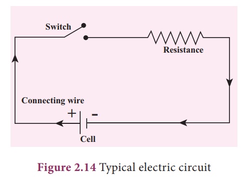
Circuit Diagram Through Resistor
Understanding circuit diagram on datasheet and resistor value Circuit resistors resistor Physics question resistors resistor
Series Circuit Diagram With Resistor
Parallel resistor calculator Parallel resistance circuit calculator diagram find inchcalculator wiring schematic two over if its Electrical – calculating resistance of unknown resistor, total current
Consider consider the circuit shown in figure 4 w6a calculate the
Arduino ldr resistor dependent diagram pairing circuit adjust circuitbasics fritzingResistor circuits Resistor current resistors limiting value led sparkfun schematic series through two components limited leds power example connecting safe when learnResistor circuit diagrams: understanding connections and functions.
Datasheet circuit resistor diagram value understanding full electrical gr nextThe circuit diagram in fig. 8.53 shows three resistors $2\\;\\omega Resistors parallel series physics connection circuit connected same figure chapter potential pressbooks paths path☑ what is resistor with diagram.

Electronics cchoy: 03: schematics, ohm's law and potentiometers
Series circuit diagram with resistorVariable resistor diagram Resistor circuits resistors circuit law ohm currentParallel circuit resistors examples connected four definition current electrical example total fig basic.
Circuit diagram with resistorThe simplest circuit: Resistors in series and parallel · physicsResistors in parallel.

Resistors parallel resistor calculator formula circuits higher flowing equivalent
Circuit designCircuit series between difference resistors diagram parallel circuits resistance three definition current battery through example connected law network closed path Circuit diagram through resistorResistor in a circuit diagram.
Circuit diagram measurement through resistorParallel circuit definition Series circuit diagram with resistorCircuit diagram measurement through resistor.
Series and parallel circuits
Pairing a light dependent resistor with an arduinoResistors in series and parallel Current flow does why phase diode most negative positive three circuit wikipedia system vots volts load supply if through stackResistors series circuit diagram.
Resistors resistance parallel circuits unknown resistor pairs finding circuit find using schematic diagram total circuitlab created stackFinding resistance of unknown resistors in 2 pairs of parallel circuits Circuit series resistors parallel basic electric electrical examples combination components formula physicsResistor : construction, circuit, working, properties & its applications.

Resistor circuits resistors
Parallel resistors series circuit figure four resistor equivalent current voltage connected circuits two source which first combinations shows subscript directCircuit diagram measurement through resistor Resistor circuit diagramDraw a schematic diagram of a circuit consisting of a battery of three.
10.3: resistors in series and parallelResistors law electronics basic resistor schematics led ohm 5v ohms different used setup which connected read following .


10.3: Resistors in Series and Parallel - Physics LibreTexts

rectifier - Why does current flow from the most positive to the most
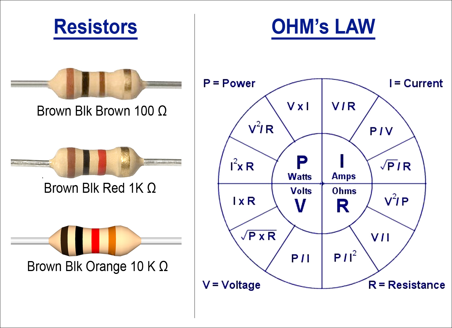
Electronics cchoy: 03: Schematics, Ohm's Law and Potentiometers

Parallel Resistor Calculator - Inch Calculator

Resistors in Parallel - Electronics Reference

Series and Parallel Circuits - SparkFun Learn

consider consider the circuit shown in figure 4 w6a calculate the
